Engineers who come to fabricated acrylic from machined metal usually bring one habit that doesn’t transfer: the blanket tolerance in the title block. On a part machined from billet in one setup, a single tolerance can be an honest statement. On an acrylic assembly, it is fiction — because an assembly mixes processes, and each process contributes its own variation to the stack. Stack-up analysis on fabricated acrylic has to be built from per-process bands, and the Acrylic Fabrication Tolerances standard publishes exactly those.
A five-sided case, three processes
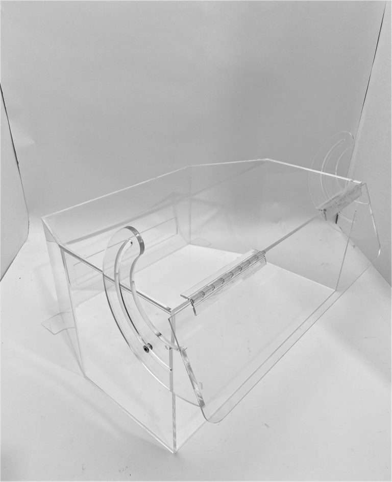
Take the workhorse of display fabrication: a five-sided bonded case. Its panels may legitimately come off different machines — large straight-cut walls from the saw, a base with routed features from the CNC, thin detailed components from the laser. Per the published standard, those processes carry different typical ranges: saw-cut components at approximately ±1/16 to ±1/8 inch, CNC-routed components at approximately ±1/32 inch, laser-cut components at approximately ±1/32 to ±1/64 inch. The assembly operation itself then adds its own contribution — fabricated assemblies run approximately ±1/16 to ±1/8 inch, because joint geometry and alignment introduce variation beyond the parts themselves.
Two more contributors belong in the stack and are routinely forgotten. Sheet thickness is a manufacturing tolerance of the material, not the shop — approximately ±10% of nominal thickness — so any dimension that accumulates across one or more sheet thicknesses inherits that variation. And thermoformed components, where the design includes them, hold formed-range tolerances of approximately ±3% to ±5% of the formed dimension, a fundamentally different kind of band than any cut part carries.
Run a worst-case stack across that case — walls, base, thickness accumulations, assembly — and the honest answer may be wider than the designer assumed from any single number on the drawing. That is not a quality problem; it is the arithmetic of a multi-process build. The design question is what to do about it.
Slot-and-tab needs designed-in clearance
Nowhere does the stack bite harder than interlocking joinery. A tab drawn at exactly the width of its slot will not assemble: by the time cutting variation on both parts, the cut’s own kerf behavior, and the film of solvent cement in the joint have stacked, a nominal-nominal fit is an interference fit somewhere in the run. The working answer is clearance designed into the joint from the start — sized at design review against the processes the parts will actually run on, which is a conversation worth having with the shop before the drawing is final, while clearance is still free. Flag the joints as functional fits on the drawing so they are part of the quote conversation from the start.
Thermal movement belongs in the stack
Acrylic moves with temperature, and a part that spans environments — fabricated in a shop, stored in a warehouse, installed in a hot storefront window — carries that movement into any assembly that constrains it. On long parts and tightly framed panels, expansion allowance is a stack contributor like any other. The expansion coefficient is a material property published on the sheet manufacturer’s data sheet; the practical move is to state the installed environment range on the drawing and let the allowance be designed in, exactly as you would for any other service condition.
Datum strategy: stop the chain
Stack-up grows by chaining — each dimension measured from the last feature inherits everything before it. The countermeasure costs nothing: dimension from one reference edge or corner, so each feature carries only its own process band instead of the accumulated chain. Then be explicit about which features are functional — the fits, the alignments, the interfaces that matter — and let everything else float at its process range. A drawing where every dimension is equally tight is really a drawing where the shop has to guess which ones you meant.
The fix is usually process selection, not tighter numbers
When a stack genuinely exceeds what the function allows, the instinct is to tighten the callouts. The better lever is usually to move the one critical part to a tighter process — shifting a saw-cut component to CNC routing narrows its contribution substantially, at a cost confined to that part, while tightening every callout on the drawing raises fabrication effort across the whole assembly for variation that mostly didn’t matter. Process selection is a cost factor the engineer controls from the drawing, and it is the reason per-process bands are worth knowing in the first place: they tell you what each move buys.
If you have an assembly where the stack math is getting uncomfortable, that is a design-review conversation, not a redrawing marathon — bring the drawing and the process plan comes back with the stack already thought through.