A custom acrylic part is almost never made by one machine. It is made by a sequence: a sheet is cut, sometimes formed, sometimes joined to other parts, its edges taken to a defined finish, and its surfaces printed or marked. Each stage changes what the next stage can do — which is why a part that gets specified stage by stage tends to fit, and a part that gets specified as a picture tends to surprise someone at assembly.
This is the map. It follows the material’s own journey through the shop, one process at a time: what each process physically does to acrylic, what geometry and quantity it suits, what its output looks and measures like, and which published standard governs that output. Read it once and you should be able to guess which processes your own part needs before you ever send it out to quote — and, more usefully, know which decisions have to be made before the first cut rather than after the first article.
Before anything is cut: the sheet
Two grades of acrylic sheet behave differently under every process that follows, and choosing between them is the first fabrication decision, not a purchasing footnote.
Cast acrylic carries the optical clarity. It routs to a clean, low-stress result, polishes to the highest clarity, holds its clarity through bends and curves, and engraves cleaner and sharper — which is why cast is the sheet we engrave. It is the usual recommendation wherever the part is display-facing or will be bonded into something people look into.
Extruded acrylic is more consistent in thickness and more cost-efficient, machines predictably, and forms predictably and economically. On cost-sensitive volume where the edge is not the product, extruded genuinely wins — and saying otherwise would cost a buyer money for no gain.
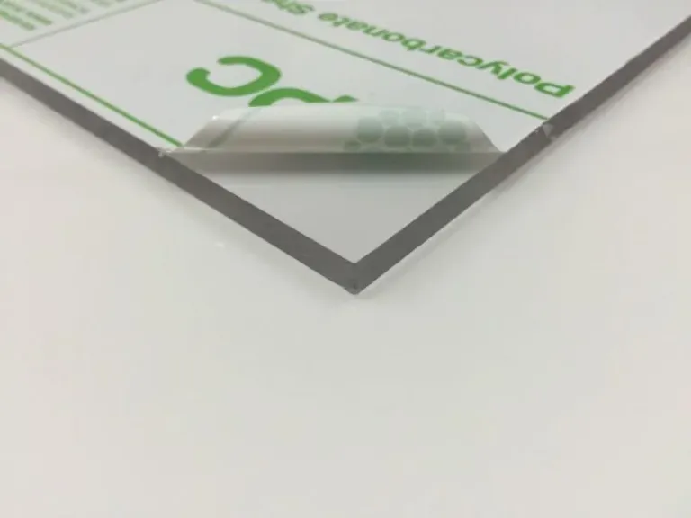
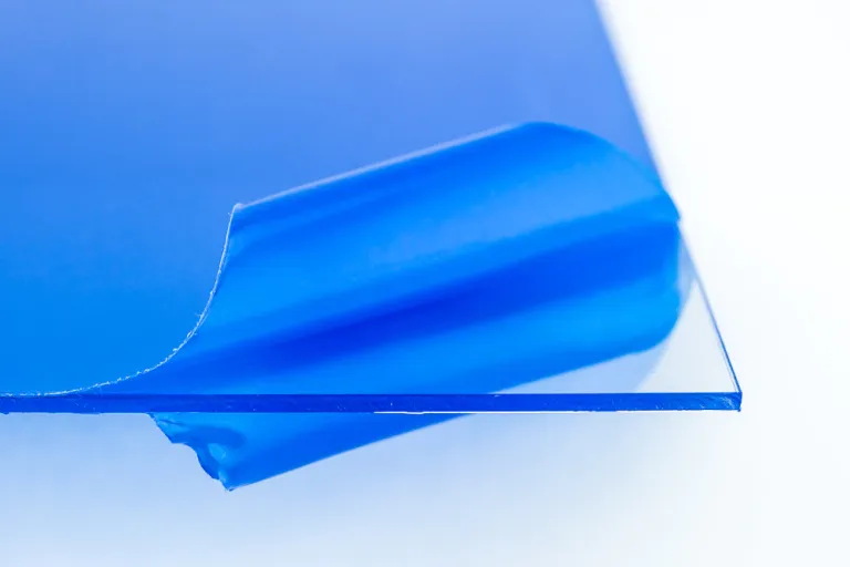
Both come clear, colored, frosted and mirrored, in all standard thicknesses, with custom sheets available when a project requires it. Acrylic is the specialty here, and complementary materials — metal, wood, hardware — get incorporated as a build requires. Grade, thickness and process are advised together at the spec stage, because they are one decision wearing three hats.
One material fact shapes everything downstream, and it is published in our Fabrication Tolerances: acrylic sheet is manufactured to a thickness tolerance of approximately ±10% of nominal. That variation exists before any fabrication begins, and it is why features that reference sheet thickness — slots a panel seats into, rabbets, tab-and-slot joinery — get designed against measured material rather than the nominal callout. A shop that machines a slot to a nominal quarter inch and receives sheet at the thin end of the band has built a rattle; designed against the actual sheet, the same joint seats every time.
Cutting: saw, CNC routing, laser
Cutting is the foundation of every acrylic build. A part that drifts out of spec here ripples into every downstream bond, fit and assembly, which is why cutting method gets matched to the geometry rather than to whichever machine is free.
Saw cutting
Straight, rectilinear panels cut to external dimension run most efficiently on the saw. This is the right method for bulk panel work — enclosure faces, glazing, fixture panels — where the outline is simple and the volume is real. The as-cut edge is relatively rough, which is fine when it is hidden or structural, and is a starting point when it is not.
CNC routing
CNC routing mechanically cuts and machines acrylic with multi-axis precision. It is the method when the geometry is thick, three-dimensional, or has to mate into something else: thicker stock that a laser cannot cut cleanly, 3D contours, pockets, slots and counterbores machined into the face, edge profiling such as chamfers and radii cut in one operation, and — critically — mating edges machined to seat flush for bonding. Full sheets nest for efficient, repeatable production runs.
Laser cutting
Laser cutting uses a focused, non-contact beam to cut two-dimensional acrylic at speed. It resolves fine detail, thin webs, delicate profiles and tight internal cutouts that a router bit cannot reach cleanly, and on cast acrylic it leaves a smooth, glossy edge straight off the bed — often needing no secondary finishing at all. Setup is fast, so a first article does not wait on tooling, and it stays fast on intricate repeating artwork, which is what holds per-unit cost down at volume.
Laser cutting is two-dimensional by nature. The moment a part needs depth, a machined pocket or a bonded mating edge, CNC is the better answer — and plenty of parts get both, laser for the intricate profile and CNC for the features.
The governing standard. Dimensional accuracy from cutting is held to the Fabrication Tolerances standard, which publishes a defined range per process — because the three cutting methods genuinely do not hold the same band:
| Process | Published typical tolerance |
|---|---|
| Saw-cut components | approximately ±1/16 to ±1/8 inch |
| CNC-routed components | approximately ±1/32 inch |
| Laser-cut components | approximately ±1/32 to ±1/64 inch |
Those are the numbers a drawing should be written against, and they are also a selection guide read backwards: if a dimension on your part genuinely needs the tighter band, the process that holds it has just been chosen for you — and if it does not, specifying the tighter process anyway is paying for precision the part cannot use.
Forming: line bending, drape forming, vacuum forming
Heating acrylic to a forming temperature lets it take a new shape over tooling and hold that shape as it cools. The result is smooth, continuous geometry with no seams and no glued joints — geometry that cutting and bonding simply cannot reach. That repertoire extends to formed hemispheres — and to full spheres, which are produced as two formed hemispheres bonded together.
- Line bending — crisp single-axis bends for folded panels, brackets, holders and box forms, where a bend replaces a joint entirely.
- Drape forming — gentle curves and radii formed over tooling, for curved fronts, wraps and contoured faces.
- Vacuum forming — deeper, dimensional shapes and repeatable contours for domes, covers, housings and enclosures.
Forming is a tooling process, and that is the honest trade. Tooling gets built or specified to your geometry so formed parts repeat across a run instead of being coaxed into shape one at a time — which means forming earns its keep on repeating programs and on shapes that have no flat-part equivalent. If a part can be made flat and bonded, and the joint is acceptable where the curve would have been, bonding is often the simpler path.
The governing standard. Formed geometry is held to the thermoformed range inside the Fabrication Tolerances standard: approximately ±3% to ±5% of the formed dimension, depending on geometry. Notice the units — a proportion, not a fixed fraction of an inch — because material stretch and thermal shrinkage scale with the size of the part, which is exactly why a formed feature written against a machining expectation ends up in dispute. Shape is locked to the tooling and defined before forming, so the fiftieth part matches the first, repeatable across the run and across the reorder.
Joining: solvent, UV-cure, mechanical, hybrid
Joining is where a program either holds together or falls apart, and where a surprising share of what goes wrong on a custom acrylic order actually goes wrong. Four methods, matched to the part, the load it carries and the cosmetic finish it has to meet.
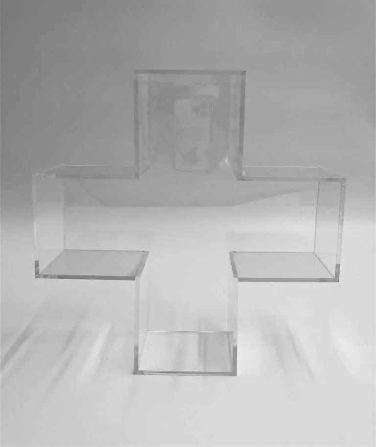
Solvent bonding chemically fuses mating acrylic surfaces into a single continuous piece. Done right the joint is structurally strong and visually near-invisible — the standard approach for clear boxes, cases and display walls.
UV-cure bonding uses a light-cured adhesive to produce high-strength, water-clear joints with controlled cure timing. It suits butt joints, detail work and assemblies where a glass-clear bond line is the priority.
Mechanical fastening — screws, standoffs, brackets, hardware — is the right answer when a joint has to carry load, mount to a surface, or come apart again. If an assembly must be serviceable, or has to knock down flat for transport, mechanical fastening beats the better-looking permanent bond outright, and that should be decided as a design intent rather than discovered at the loading dock.
Hybrid joining combines fastening with adhesive at points that carry load, attach hardware, or join acrylic to metal, wood and other materials in one assembly.
Joint preparation is part of the method rather than an afterthought: mating edges are cut and finished to spec so the surfaces seat cleanly.
The governing standard. Bond lines are held to defined criteria in the Joint Clarity Standards, so “seamless” is a documented specification rather than a sales word. Assembled fit — panels aligning, lids seating, units stacking predictably across a run — is held to the fabricated-assembly range in Fabrication Tolerances: approximately ±1/16 to ±1/8 inch, deliberately wider than any single machined part’s band, because an assembly stacks the variation of every component and every joint inside it. A drawing that puts a single-part tolerance on an overall assembly dimension is asking the parts to cancel each other’s variation out, which they will not reliably do.
Edge finishing: from as-cut to optically clear
The edge is what separates a part that looks fabricated from one that looks finished. The Edge Finishing Standards define six classifications — raw/saw-cut, sanded, laser-cut, flame-polished, buff-polished, and diamond-polished — and the useful way to read that list is as two separate things a spec tends to collapse into one ranking: the condition the edge arrives in from cutting, and the finishing method applied afterwards.
The starting condition
- Raw or saw-cut — a relatively rough as-cut edge. Correct as it stands for hidden and structural edges, and the usual starting point for anything that will be finished.
- Laser-cut — on cast acrylic at appropriate thicknesses, a crisp, flame-like edge that often needs little or no secondary finishing at all. It is not a lower rung than sanding — it can arrive display-ready with no finishing step, which is part of why cutting method gets chosen with the edge in mind.
The finishing method
- Sanded — a uniform matte-to-satin surface. Specified where the edge has a job to do: it gives solvent and UV adhesives a flat, uniform, low-stress seat for stronger, more consistent joints, scatters light evenly to soften hot spots in edge-lit builds, and reads as a deliberate non-glare detail.
- Flame-polished — a controlled flame passed across the cut edge takes it clear and glossy in a single pass. Fast and efficient on straight edges at volume; it can soften crisp corners, and it is harder to hold dead-flat on thick stock.
- Buff-polished — a mechanical, multi-stage process refining the edge against rotating wheels to a clear, glossy finish. Because it is machine-driven rather than heat-driven, it is controlled and repeatable on thicker stock and across long runs, and it does not introduce the internal stress that heat-based methods can.
- Diamond-polished — a diamond-tipped cutter shears the edge to an optically flat, transparent surface in a controlled pass. The clearest, flattest edge acrylic can hold, and the method when the edge is the part people look into rather than at.
The practical question is not “which finish is best” but “where will this edge be seen” — display-facing, a bonding face, or hidden structural. Answer that per edge and the method follows. Most real parts carry more than one: edges that bond get sanded, edges that are seen get polished, on the same piece. The pairing to the quality grades is predictable too — Production-grade work commonly carries sanded or flame-polished edges, Display-grade work steps up to buff-polished, and Museum Archival work typically requires diamond polishing — so naming the grade a surface must meet goes a long way toward naming the edge method that reaches it.
Printing and marking: UV, screen, vinyl, engraving
Print and mark are surface processes, and they are the last place where a part’s identity gets added.
UV printing puts full-color graphics directly on acrylic. The ink reacts to UV light and sets instantly — no solvent off-gassing, no air-dry or heat-cure wait — producing bright color that holds fine type and gradients alongside bold fills, and resists scratching, abrasion and fading. A white layer prints as a flood or an under-base so color stays opaque on clear, colored and frosted stock. Second-surface printing puts the graphic on the back face, so it reads with glass-like depth and is physically protected from handling. Color is color-managed CMYK matched to the brand references you supply, confirmed at proof approval before the run.
Screen printing lays a denser, more durable ink film. Where a few solid brand colors run across a large quantity, screen printing beats UV on both durability and per-unit cost at volume: once the screen is made, high quantities print economically. A genuine win for the other method, and worth asking about when your artwork is simple and your volume is not.
Vinyl graphics suit flexible, seasonal and changeable campaign artwork, applied first- or second-surface.
Engraving is marking rather than printing. Laser engraving is surface-level and resolves the finest detail — fine text, frosted graphics, high-resolution logos. CNC engraving cuts deeper recesses for bold, tactile results: V-carved lettering, pockets for paint-fill, dimensional detail that reads at distance and survives handling. Engraved work runs on cast sheet, because cast engraves cleaner and sharper; if a part will carry engraving, that decides the sheet grade before anything is cut.
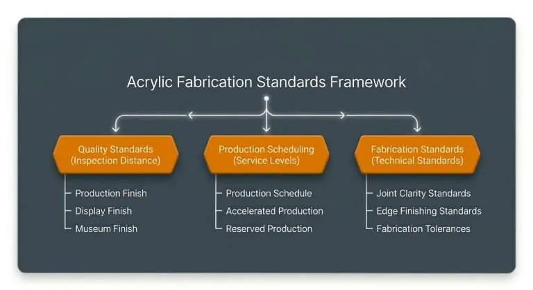
The governing standard. Printed and marked surfaces are graded by the Quality Standards — Production, Display or Museum Archival — chosen by Inspection Distance, the published viewing distance the surface is judged from: approximately 4 feet, 2 feet, and 1 foot respectively. Print placement and registration are held to Fabrication Tolerances, so artwork lands in the same place across the run.
The interaction effects most process guides skip
Each of the above is a clean story on its own. The value is in the seams between them, where the order of operations quietly decides what is still possible later.
Diamond polishing is a pre-assembly decision. It is performed on flat sheets and parts before they are bonded, and it cannot be added to an assembled product afterward. Flame polishing, by contrast, can be applied almost anywhere, including on already-bonded work. So if an edge needs the diamond-polished level, that gets decided at the spec stage — before any bonding — not admired on a sample and requested after the piece is built.
Edge finish is a bonding decision, not a cosmetic one. A sanded face gives solvent and UV adhesives the flat, uniform, low-stress seat a joint wants, which is why the mating edges on a bonded assembly get specified deliberately rather than defaulting to whatever the cutting method left behind. Joint clarity and joint strength both start at the edge; the edge level and the joint criterion belong in the same conversation.
Heat is the common thread to watch. Heat-based finishing carries internal stress that machine-driven finishing does not, and on thicker stock a heat-polish is where crazing and stress risk concentrate — which is precisely why buff polishing is specified on thick display-facing edges instead.
Annealing is the stress answer, and it is a step, not an assumption. Cutting, machining, drilling and forming all leave stress in the material, and stress plus solvent is what crazing is made of. Annealing is a controlled heat cycle that relieves it before the part goes on to bonding, which is why the sequence on machined work runs anneal, then bond, then any heat-polish after. On a recurring program the cycle is written into the documented spec so the tenth lot behaves like the first article. If a part will be bonded, ask whether annealing is in its route; if it matters to you, put it on the drawing.
Formed parts do not measure like machined parts. A thermoformed radius and a routed pocket are held to different published ranges for good reason: one is shaped over tooling as the material cools, the other is cut by a spindle. Writing a formed feature against a machining expectation is one of the most common ways a drawing and a part end up disagreeing.
Material choice reaches all the way downstream. Cast acrylic is chosen at the sheet stage for an edge that will not exist until the finishing stage. That is a purchasing decision made on behalf of a process two or three steps later, which only works when the whole sequence is specified up front.
Reading your own part
| If your part needs… | The likely process | The governing standard |
|---|---|---|
| Straight panels cut to exact outside dimension | Saw cutting | Fabrication Tolerances |
| Thick stock, pockets, 3D contours, mating edges | CNC routing | Fabrication Tolerances |
| Fine detail, tight internal cutouts, intricate repeats | Laser cutting | Fabrication Tolerances |
| Curves, domes, wrapped edges, seamless geometry | Thermoforming | Fabrication Tolerances (thermoformed ranges) |
| A clear box, case or display wall | Solvent or UV-cure bonding | Joint Clarity Standards |
| An assembly that must be serviceable or ship flat | Mechanical or hybrid joining | Fabrication Tolerances (assembled fit) |
| An edge that is seen, bonds, or diffuses light | Edge finishing, level per edge | Edge Finishing Standards |
| Full-color brand graphics on the part itself | UV printing | Quality Standards |
| A fixed in-hands date | Reserved Production | Production Scheduling |
Four of the five standards in that column govern something physical about the part. The fifth governs the calendar, and it is the one buyers most often assume rather than specify.
Why the sequence runs under one roof
Every process above happens in-house, US-made. That matters most on multi-process parts, which is nearly all of them: a display that is laser-cut, line-bent, solvent-bonded, sanded on its bonding faces, diamond-polished on its show edges and UV-printed touches six processes. Split across vendors, each transition is a shipment, a queue and a re-quote, and the interaction effects above become somebody else’s problem to discover. Under one roof they are decisions made once, at the spec stage, by the people who will run every machine. It is the same sequence, dialed to different grades and volumes, behind OEM components for Motorola and Bosch, instrument cases for Stryker Instruments, and museum casework that went to the Whitney Museum of American Art — finished multi-process work is worth a look in the gallery, and the sequence underpins recurring retail and POP display programs as well.
Scheduling is specified the same way as everything else, through Production Scheduling — and on a six-process part, Reserved Production, the one tier that guarantees a specific ship date, is worth asking about early.
Specifying it from here
You do not need to arrive with the process sequence solved. The useful inputs are the ones that determine it: the part’s geometry, where each edge will be seen, what it has to join to, whether it carries graphics, the quantity now and the quantity next quarter, and the date. For quoting, PDF is the preferred file format and DXF and DWG are accepted; dimensioned drawings are welcome alongside, and artwork travels as AI, EPS, SVG, PNG or JPG. A clear concept and dimensions are enough to start.
If you have a part in mind and want the process path, the governing standards and a production tier confirmed before anything is committed, send it over and we will scope it.