Search for “acrylic tolerance” and the results answer two different questions as if they were one. Half of them talk about how much a sheet’s thickness can vary from the number printed on the pallet. The other half talk about how precisely a fabricator can cut, drill and assemble a finished part. Both are real, both matter, and a drawing that only addresses one of them is a drawing that will produce a surprise. This post separates the two numbers, says where each one comes from, and shows how to write both so the part fits.
Number one: what the sheet maker guarantees
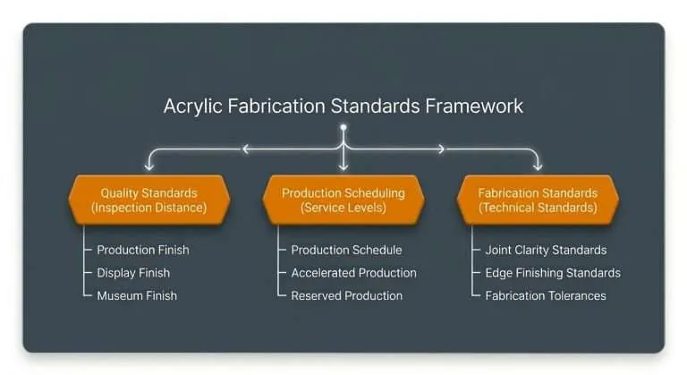
Acrylic sheet is manufactured to commercial material tolerances, and the one that bites most often is thickness. A sheet sold as 1/4 inch is not 0.250 inches everywhere; it is 0.250 nominal, with a permitted variation around it. The Acrylic Fabrication Tolerances standard records the typical material tolerances as approximately ±10% of nominal thickness, and approximately ±1/8 inch on sheet length and width. Those variations originate at the sheet plant, before a fabricator ever touches the material, and no cutting process downstream changes them.
The exact figure for a given sheet is the manufacturer’s to state, and it may vary by product, by manufacturer and by production method. Cast and extruded sheet are made differently and each manufacturer publishes its own thickness tolerance for each product line; the cast vs extruded post covers what else separates them. If thickness is critical to your part — and the next section explains when it is — the data sheet for the specific product is the document to read. Ask for it in the specification. We tell specifiers to request the manufacturer’s data sheet and, where the batch matters, the lot certificate, as a line in the spec; they are not something that travels with every order by default, so the spec is where the request belongs.
Number two: what the fabricator holds
The fabricated tolerance is the variation in the finished part’s dimensions — cut lengths, hole positions, assembled widths — and it depends on the process used, not on the sheet. The standard publishes a typical range per process:
- Laser-cut components: approximately ±1/32 inch to ±1/64 inch
- CNC-routed components: approximately ±1/32 inch
- Saw-cut components: approximately ±1/16 inch to ±1/8 inch
- Fabricated assemblies: approximately ±1/16 inch to ±1/8 inch
- Thermoformed components: approximately ±3% to ±5% of the formed dimension, depending on geometry
Notice what these ranges describe: the dimensions a process creates. A laser can hold a cut length to approximately ±1/32 inch on a sheet whose thickness varies by a tenth of its nominal value, because the cut length and the sheet thickness are independent. This is the part that confuses buyers who have read the thickness tolerance and assume everything about the part is loose. The width of a laser-cut panel is tight. Its thickness is whatever the sheet was. The tolerances by process post walks through why each process lands where it does.
Where the two numbers collide
The trouble starts where a fabricated dimension is sized against the sheet’s nominal thickness. Three places this happens constantly:
Slots and tabs. A tab cut from 1/4-inch sheet is designed to fit a slot cut 0.250 wide. The slot is cut on a laser or CNC and comes out very close to 0.250. The tab is the sheet, and the sheet may be anywhere in its permitted thickness range. On the thick end the tab will not enter the slot; on the thin end it rattles. Neither the slot nor the tab is out of tolerance — the design assumed a thickness the sheet maker never promised.
Edge-joined assemblies. A five-sided box bonded from sheet has outside dimensions that depend on the panel widths plus two sheet thicknesses. The widths are fabricated dimensions and tight; the thicknesses are sheet dimensions and are not. The assembly band of approximately ±1/16 inch to ±1/8 inch in the standard exists partly for this reason.
Stacked layers. Risers, laminated blocks and stepped displays built from several layers accumulate the thickness variation of every layer. Five layers of nominal 1/2-inch sheet are not a 2-1/2-inch stack; they are a stack somewhere in the range five sheet tolerances allow.
The design moves that keep sheet variation from becoming fit trouble are not exotic. Size slots to the sheet’s real range, not its nominal, or add a small clearance and accept a non-interference fit. Reference assembled dimensions to outside faces where the thickness falls inside the dimension rather than adding to it. Where a stack height genuinely matters, specify the finished stack height as the controlled dimension and let the fabricator select or machine to it. In each case the fix is a line on the drawing that acknowledges which number governs that feature.
How to write both on the drawing
Specify the finished-part tolerance where it matters, feature by feature: the hole pattern that meets customer hardware, the slot that locates a mating part, the overall width that has to enter a frame. Leave the rest to the typical ranges the standard publishes per process. The tolerance callouts post gives the drawing-note pattern that gets this across in one line.
Then, separately, handle thickness. If nominal thickness is fine — and for most displays, enclosures and fixtures it is — say nothing and the sheet’s commercial tolerance applies. If thickness is critical, say so explicitly, state why (a slot fit, a stack height, a mating part), and put the request for the manufacturer’s data sheet in the spec so the real range is on file before the material is ordered. A drawing that does both has addressed both numbers, and the part that comes off it fits for a reason rather than by luck.
Not sure which of your dimensions depend on sheet thickness? Send the drawing — identifying those features is part of the file review every RFQ gets.