Most acrylic drawings that cause trouble in fabrication fail in one of the same ten ways. None of them are exotic. They are habits carried over from machined metal or injection-molded plastic, applied to a material that behaves like neither — and every one of them is free to fix while the part is still in CAD, and expensive to fix after the first article is cut.
Here is the list, in the order we most often catch them at quote review.
1. Sharp inside corners
Acrylic is notch-sensitive: a sharp internal corner concentrates stress at a single point and becomes the starting site for a crack — under fastener load, thermal cycling, an impact, or contact with a solvent or cleaner. The failure often shows up months after delivery, radiating from exactly the corner the CAD model drew at zero radius. The fix: design a radius into every inside corner. Even a small one spreads the load and removes the crack-start geometry, and it costs nothing to cut.
2. Blanket tight tolerances
A single tight tolerance in the title block applies itself to every feature on the part, and that forces every feature onto the tightest — and slowest — process, whether it matters or not. The published typical bands span a wide range for a reason: laser-cut features hold approximately ±1/32" to ±1/64", while saw-cut dimensions run approximately ±1/16" to ±1/8", and fabricated assemblies approximately ±1/16" to ±1/8". A blanket callout erases those distinctions and prices the whole part as if every edge were a functional fit. The fix: tolerance only the features that actually mate with something, and let everything else carry the standard bands in our Fabrication Tolerances standard.
3. Threads tapped into thin acrylic
Tapped threads work in metal because metal yields; acrylic does not. Threads cut into thin acrylic strip under modest torque, and the tapping operation itself leaves a stressed, notched bore that is a crack waiting for a load path. The fix: use threaded inserts, standoffs, or through-hardware with the fastener bearing on a washer — put the threads in metal, and let the acrylic do what it is good at.
4. Ignoring sheet yield
Acrylic parts are cut from standard sheets, so the parts-per-sheet math is set the moment you pick your dimensions — and a dimension chosen at random can land just past the line where one fewer part fits per sheet. The part did not get better; the material economics got worse, on every sheet, for the life of the program. The fix: before freezing dimensions, check how the part nests. If a dimension has any flexibility, ask us which nearby dimension yields better — on recurring work, that one question compounds.
5. Polished edges specified on hidden faces
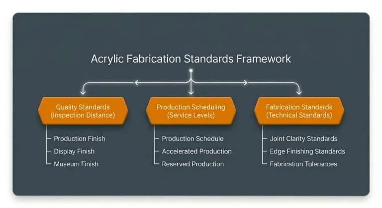
"Polish all edges" is the finishing equivalent of a blanket tolerance: it buys hand labor on faces that will spend their service life against a wall, inside a joint, or under a mounting flange. Polishing is a per-edge operation, and every hidden edge polished is finishing effort nobody will ever see. The fix: grade each surface by how closely it will actually be inspected. Our Quality Standards define grades by Inspection Distance — Production Finish at approximately 4 feet, Display Finish at approximately 2 feet, Museum Archival Finish at approximately 1 foot — and the Edge Finishing standard maps six edge classifications onto them, so a drawing can say precisely which edges earn the polish.
6. No thermal-expansion allowance in fastened frames
Acrylic moves with temperature considerably more than the aluminum or steel it usually gets bolted to. Pin a panel through tight holes at all four corners and the frame wins every seasonal argument: the panel cannot move, so stress builds at the fasteners until a crack relieves it — at the bolt holes, right on schedule. The fix: slot or oversize the mounting holes and let the fastener clamp through a washer, so the panel is held flat but free to move.
7. Raster logo art supplied for print
A logo pulled from a website is sized for a screen; printed across a flatbed-scale display face, its pixels are the artwork, and the output reads soft no matter how good the printing is. This is the one mistake on this list that is invisible in CAD and unmissable on the finished part. The fix: supply vector artwork — AI, EPS, or SVG — for anything with edges or type, and reserve raster files for photographic imagery supplied at final print resolution.
8. Missing thickness callout
A drawing without a thickness callout is not a lean drawing — it is an unquotable one, because thickness drives material cost, weight, stiffness, and which edge treatments are practical. It also hides a downstream trap: sheet thickness itself carries a tolerance of approximately ±10% of nominal, so any slot or channel another part fits into has to accept that band, not the nominal number. The fix: call out nominal thickness on every part, and size mating slots for the thickness range rather than the nominal alone.
9. Pre-offsetting geometry for kerf
Some drawings arrive with every profile grown or shrunk by half a cut width, because the designer knew the laser removes material and tried to help. The shop’s CAM software already compensates for kerf on every path — so pre-offset geometry gets compensated twice, and every dimension lands off by a full kerf width in the wrong direction. The fix: draw the part at nominal, exactly as you want it to measure. Process compensation is the fabricator’s job; the published bands in the tolerances standard already describe what the compensated process holds.
10. Uniform wall thickness specified on a deep formed part
Thermoforming stretches a flat sheet over or into a form, and the material for the deep sections has to come from somewhere — so walls thin as the draw gets deeper, unavoidably and by geometry, not by workmanship. A drawing that specifies one uniform wall on a deep formed part specifies something the physics will not deliver; formed dimensions also move more than cut ones, at approximately ±3% to ±5% of the formed dimension depending on geometry. The fix: specify the starting sheet thickness, the finished geometry, and the locations where a minimum thickness genuinely matters — then let the forming process be engineered to hit those.
The meta-fix: review before the drawing freezes
Every mistake above shares one property: it is a CAD edit before the drawing is frozen, and a re-quote, a re-cut, or a field failure after. The ten fixes are individually simple, but the reliable way to catch all of them — plus the eleventh one specific to your part — is to have fabrication eyes on the drawing while it can still change. Send the drawing over before you freeze it (PDF preferred; DXF or DWG accepted) and we will review it against the standards linked above as part of quoting. Start with the drawing you have — flagging these at the quote stage is the cheapest engineering hour in the whole project.