Acrylic bench-top shields are everyday equipment in labs that work with beta-emitting isotopes, and they occupy an unusual spot in custom fabrication: the most important line of the spec — material and thickness — is not the fabricator’s to write. So let’s state the responsibility split plainly, first, because everything else in this post sits on it: your lab’s safety officer specifies the shield’s material and thickness for the isotopes in use; Akrylix fabricates precisely to that specification. This post never recommends a thickness for a radiological purpose, and neither should any fabricator. What a fabricator legitimately owns — and what this post covers — is everything that makes the specified shield accurate, durable, and pleasant enough to work behind that it actually gets used.
The common shield formats, as fabrication objects
Set the radiological function aside and a beta shield is a formed and finished acrylic object, and the common formats each have a distinct build:
- Flat bench-top shields with an angled viewing face — the standard personal shield: a vertical lower section, a bend partway up, and an angled upper face the user looks through while pipetting behind it. These are line-bent from a single sheet: the bend line is heated locally until the material softens, formed to the specified angle, and cooled in position. One sheet, no joints in the sightline.
- L-shaped body shields on stable bases — larger shields that stand between a worker and a bench area, formed or bonded to a base footprint that keeps a tall panel stable. The engineering here is mundane and important: base geometry and material mass are what keep a shield from tipping when bumped.
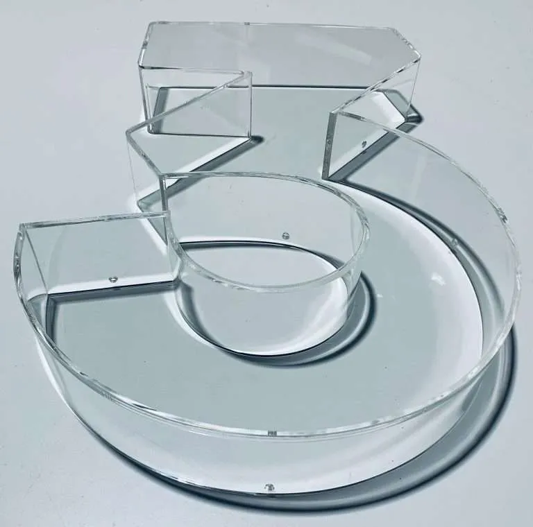
- Box enclosures over sources or procedures — five-sided bonded covers, fabricated like any precision acrylic enclosure: panels cut to dimension, edges prepared, joints bonded, corners finished.
- Lid and port variants — any of the above with machined pass-throughs, hinged lids, or access openings, cut before forming so the geometry lands where the drawing says.
Why fabrication quality matters to the user every day
Here is the practical truth about lab shields that specification documents rarely say out loud: a shield only does its job while it is between the user and the work, and users push aside equipment that fights them. A shield with a hazy viewing face, scratched-up surfaces, or rough edges gets nudged out of the sightline within a month — which defeats its purpose entirely. Fabrication quality is what prevents that. Polished edges that are comfortable near hands and forearms; a viewing face held to a clean finish grade — Display Finish or better from our Quality Standards is the sensible ask for the face someone reads graduations through; a bend placed so the user looks through the angled face at their natural working posture rather than crouching to it. None of that is radiological. All of it determines whether the shield is in position on a Tuesday afternoon in month eight.
Geometry details worth specifying
When a shield order goes wrong, it is almost never the material line — it is the geometry nobody wrote down. The practical checklist:
- Base footprint vs bench depth. The shield has to share a working bench with racks, pipettes and waste containers. Measure the depth actually available, and the working zone the shield must enclose.
- Bend placement relative to working height. The angled face should meet the user’s sightline at their real posture — seated or standing at the actual bench height. A shield bent for a standing user, placed at a seated station, puts the bend zone — the one region of the shield with formed distortion — exactly where the seated user needs to see.
- Viewing-face angle. Specified in degrees, chosen with posture and overhead lighting in mind (a steeper face catches more ceiling glare).
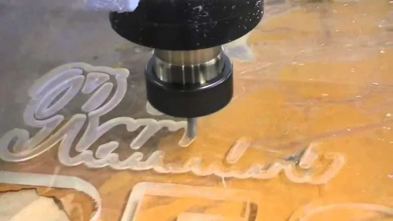
- Cutouts and ports, machined before forming. Cable ports, tubing pass-throughs and hand clearances are CNC-cut in the flat, so they land accurately after the bend — retrofitting holes into a formed shield is worse in every way.
- Edge treatment. Comfortable finished edges where hands and forearms live, per the standard edge methods.
All of it is held to the machining and forming ranges in our Fabrication Tolerances standard — which matters most on the next item.
“Five more like this one”: duplicating an existing shield
A large share of shield orders are duplications: a lab has one shield that works — right height, right angle, right footprint, everyone likes it — and wants more of it for new stations or a second lab. The workflow is measure-and-replicate: the physical sample (or a good drawing of it) becomes a dimensioned drawing, the drawing is approved by the lab, and the duplicates are fabricated to it, held to the published machining tolerances so the copies genuinely match. Two notes for whoever manages this: first, the material and thickness of the duplicates still get confirmed against your safety office’s current spec — a shield bought years ago is not automatically today’s requirement, and that confirmation belongs to your safety officer, not to us or to the sample. Second, once the drawing exists it stays on file, and station six next year is a reorder, not another measuring session.
The close, repeated on purpose
The split this post opened with is worth closing with, because it is the honest boundary of the relationship: performance verification is the customer’s domain — your radiation safety office specifies and verifies what the shield must do; drawings and fabrication are ours — executing that specification precisely, in shields accurate enough to trust and finished well enough to stay in position. When your safety officer has written the spec, send it over with the bench measurements and the drawing comes back for approval before anything is cut.