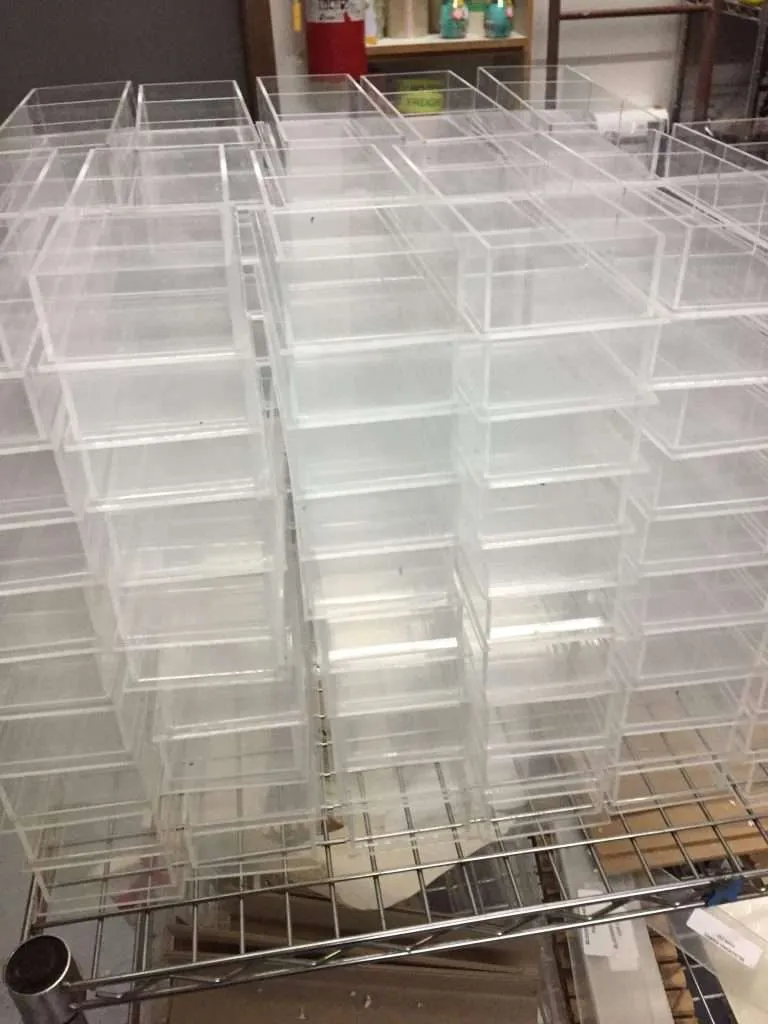
Some of the most expensive lines on a fabrication drawing are the ones that were free to draw. A perfectly square inside corner costs nothing in CAD — every drafting tool defaults to it — and yet it asks something of the physical world that rotating cutters cannot do and stress concentration punishes. Kerf is the same story in reverse: invisible in CAD, real at the machine, and occasionally the source of a part that’s mysteriously snug everywhere. This post is about the small geometry of cutting — radii, kerf, allowances — and about the drawing philosophy that handles all of it cleanly: specify intent, not toolpath.
Why inside corners carry a radius
Two independent reasons, either sufficient alone.
The tool is round. A CNC router cuts with a rotating cylindrical tool, so every inside corner it produces carries the tool’s radius — a physical fact, not a quality setting. An inside corner drawn dead-square on a routed part is a corner the process cannot make; what happens next is a drawing question back to you before anything is cut. Drawing a real radius — one comfortably at or above the radius of a reasonable tool — turns the corner from a conflict into a specification.
Stress concentration. Acrylic concentrates stress at sharp corners — and this reason applies to every process, including the laser, which can cut a nearly sharp inside corner. A sharp inside corner is a stress riser — the point where a crack starts under load, under thermal cycling, or during assembly. A radius spreads that stress. On parts that carry load, get handled, or take fasteners near the corner, the radius isn’t a machining concession; it’s the design protecting itself. The practical rule: radius every inside corner you can, generously where structure matters — and where a corner truly must be sharp, expect a conversation about process and about whether the function can be met another way (a relief, a different joint, a bonded construction that moves the corner).
Kerf: the material the cut consumes
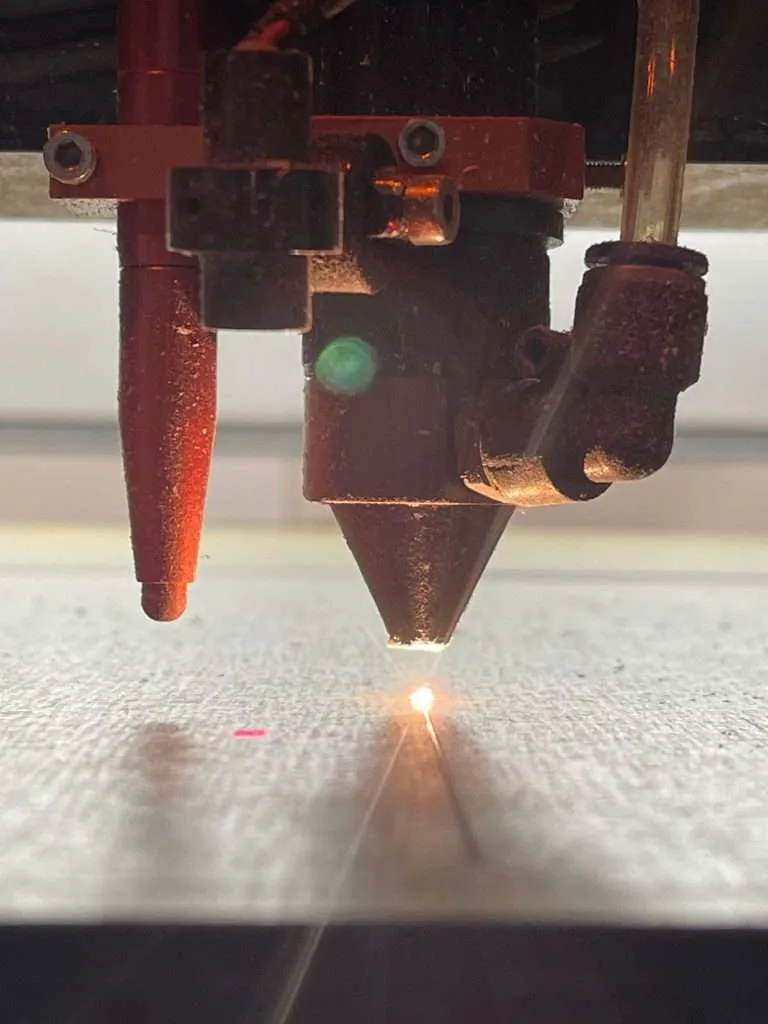
Every cutting process removes a path of material — the kerf. Saws remove a blade’s width, routers a tool’s diameter, lasers a narrow melt line. Two implications for your drawing:
First, parts are not the negative space of other parts. The classic error: designing a lid and an opening from the same rectangle and expecting a working fit — the kerf was spent making them, and clearance between mating parts must be designed, not inherited from the CAD boolean. State the clearance you want between mating parts; don’t encode it implicitly in coincident geometry.
Second, kerf compensation is the fabricator’s job — when the drawing lets it be. Shops offset toolpaths so the finished part matches the drawn dimension; that’s routine. It goes wrong when a designer pre-compensates — drawing parts oversize “to allow for the cut” — and the shop compensates again. The finished part should be dimensioned at its finished size, full stop. If you’ve added allowance anywhere for any reason, say so on the drawing in words, because silent allowances are how parts end up compensated twice or not at all.
Processes differ — and the drawing shouldn’t pick one prematurely
Cut precision and edge character vary by process, and the published Fabrication Tolerances standard defines a typical range for each rather than one number for everything — laser and CNC hold the tightest bands, saw cutting the widest, with assemblies and formed parts carrying their own ranges. Cite the standard on your drawing instead of restating its rows: the standard stays the single source when it’s revised, and your drawing stays honest. Edge character varies the same way — laser edges come off the machine glossy with a slight taper through thickness; routed edges arrive machined and uniform, ready for finishing up the edge-finishing ladder where the spec calls for it; saw cuts are the workhorse for straight lines headed into assemblies.
Here is why those ranges argue for restraint on your drawing: the process is usually the fabricator’s variable, chosen against quantity, geometry, thickness, and finish requirements together. A drawing that says “laser cut” in the title block has quietly made a manufacturing decision that might be wrong at your real quantity — the same geometry could move to CNC with fixtures at volume. A drawing that instead states the requirements — dimensions and tolerances where they matter, edge finish per visible edge, material and thickness — leaves the shop free to pick the process that meets them most economically, and accountable for meeting them. Specify the outcome; let the process serve it.
One more geometry class deserves a flag rather than a rule: small holes and fine slots. Features whose size approaches the material thickness behave differently by process — heat-affected edges, tool access, and material behavior all start to matter at once — so a drawing dense with fine features is a process conversation, not a default. Flag them, and expect the shop to propose the process that serves them.
What your drawing should specify
The distilled checklist, in drawing order rather than importance order — everything on it earns its line:
- Finished dimensions, at finished size, with units declared and governing dimensions identified.
- Selective tolerances — tight callouts only on locating features and fits, the published per-process ranges everywhere else. A drawing toleranced tight everywhere is toleranced nowhere.
- Inside-corner radii, drawn explicitly — generous where load lives, at-or-above tool radius where routing is plausible, with truly-sharp corners flagged as the deliberate exceptions they should be.
- Designed clearances between mating parts, stated as dimensions, never implied by coincident geometry.
- Edge finish per edge condition, named from the six-method standard — the callout that decides where finishing labor goes.
- Material and thickness — thickness always, “thickness” always (the word, and the number).
- What you deliberately left out — a note that unstated radii are fabricator’s discretion, or that no kerf allowance is included, costs one line and prevents the two most common silent misunderstandings in cutting.
A drawing built this way reads as intent: here is the object, here is what matters about it, here is where the process is free. Those are the drawings that quote fast, cut clean, and never generate the which-version-is-real email. If you’ve got one on your screen now — especially one with a square inside corner you’ve been meaning to think about — send it over; a drawing review before release is cheap insurance, and it’s the kind we enjoy writing.