Everything else in acrylic fabrication is subtraction and assembly — cutting sheets smaller, joining pieces together. Thermoforming is the exception: it is how acrylic escapes flatland. Curved display faces, domes, scoop bins, formed trays and covers, the sculptural work that makes people ask “how is that one piece?” — all of it starts as a flat sheet and a heated tool room. Here is the process, walked through honestly, including the parts that surprise first-time buyers.
The process walk
The sequence is the same across variants: the sheet is heated to its forming temperature range — hot enough to drape and take a shape, below the point of damaging the material — then shaped against a mold, held while it cools and locks the geometry, and finally trimmed from a formed blank into a finished part.
The variants differ in how the sheet meets the tool:
- Drape forming — the heated sheet is laid over (or into) a form and gravity plus fixturing do the shaping. The gentlest variant, used for simple curves, bends with large radii, and cylindrical wraps — most simple-curve display work is drape formed.
- Vacuum forming — the heated sheet is sealed against the mold and air is pulled out, so atmospheric pressure presses the sheet into the tool’s detail. This is the route to deeper draws and more defined geometry than drape can deliver.
- Pressure-assisted forming — compressed air added above the sheet pushes harder than vacuum alone can, sharpening detail and definition where the design demands it.
Which variant a part gets is a fabrication decision made from its geometry — depth of draw, tightness of detail, and how the optical surfaces must come out.
The mold is the real product
A formed part can never be better than its tool: the mold defines the geometry, the surface it touches, and the repeatability of every part after the first. That is why tooling is the threshold decision of any formed design — the point where a project commits.
The practical shape of the decision: tooling built for a prototype or short run is made economically, expecting to produce a handful of parts; production tooling is built for dimensional stability and surface quality across a long run, and it costs accordingly in time and effort. The factors that move the decision are quantity (how many parts will amortize the tool), geometry (deep or detailed draws demand more from the tool), and surface expectations (the mold-side finish transfers to the part). None of this should scare a buyer off forming — it should just be decided consciously: a formed design is a commitment to its tool in a way a cut-and-bonded design is not, and the moment to weigh that is before the geometry hardens.
What forming does to the material
Forming is honest physics, and three of its effects belong in every formed part’s design conversation:
- Thinning. The sheet stretches to cover the mold, and stretched material is thinner material — deepest draws thin most. A part specified as a given sheet thickness is that thickness where it didn’t stretch; over a deep draw it is less. Designs with structural or optical requirements in the drawn regions need that accounted for at CAD, not discovered at inspection.
- Tool-side marking. The surface touching the mold can pick up evidence of the contact — which makes “which side faces the tool” a genuine design decision on transparent work. The show surface should generally be the free surface, and a designer who marks the show face on the drawing has just prevented the most common formed-part disappointment.
- Optical change. A formed region is a lens — curvature bends what you see through it. Usually that is the point (a curved display face is chosen for exactly this presence); occasionally it fights the function, and a viewing-critical flat zone should stay flat.
One process note buyers ask about: material preference. Where a customer has a preference about the sheet that gets formed — brand, grade, or type — we honor it where practical; bring it up at the quote and it becomes part of the spec.
Trim is half the job
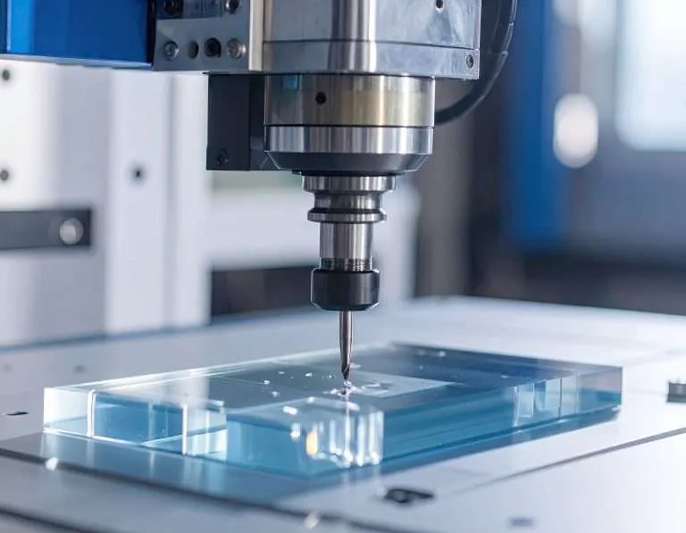
What comes off the mold is not the part — it is a formed blank with excess material where the sheet was held. The blank returns to machining for trimming to final size: edges cut back to the drawing, mounting holes and features machined, the formed geometry married back to precise flat interfaces. On many formed parts, the trim fixturing and machining consume as much planning as the forming itself, and it is where final dimensions actually get held.
Which brings up the number every formed-part drawing should be dimensioned against: formed geometry carries wider dimensional variation than machined flat work. Our published Fabrication Tolerances standard puts thermoformed components at approximately ±3% to ±5% of the formed dimension depending on geometry — an honest range reflecting material stretch and thermal shrinkage — while the trimmed, machined features on the same part hold machining-grade bands. A well-dimensioned formed drawing uses both: forming tolerances on the formed geometry, machining tolerances on the trimmed interfaces, and no pretense that a drawn curve holds a machined number.
Where forming earns its place
The decision logic in one paragraph: forming pays when the shape cannot be cut and bonded convincingly (continuous curves, domes, compound geometry), when a run is long enough to amortize its tool, or when a one-piece formed part replaces an assembly’s worth of joints. It costs a tooling commitment, wider tolerances on the formed geometry, and design attention to thinning and tool-side surfaces. Plenty of curved-looking work is honestly better served by line bending or bonded flat construction — and a fabricator worth partnering with will say so at the quote. If a formed shape is on your drawing board, bring the geometry early, while the tooling decision is still cheap — and see the formed work in the gallery for what the process delivers when the design and the tool agree.