The typical first drawing from a research group is designed by someone fluent in CAD who has never sent a part to a fabrication shop — a grad student or research engineer who models the fixture the way a machinist would mill it from billet. The part that comes back works, usually, but it cost more and took longer than it needed to, because sheet fabrication follows different rules than subtractive machining from stock. Learn the rules once and every fixture after the first gets cheaper, faster, and easier to revise.
The mindset shift: cut sheet, not milled billet
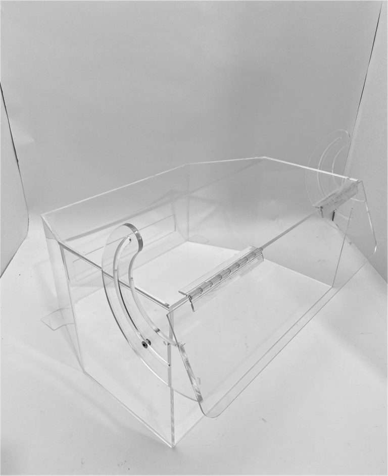
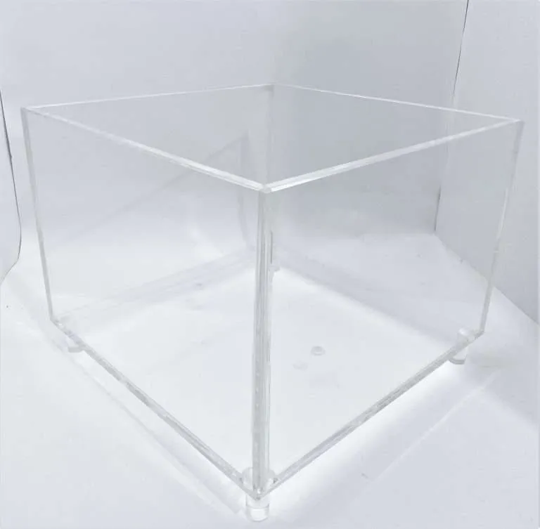
Picture the same instrument cradle designed two ways. The billet version is a block with a pocket carved out of it — deep machining, lots of material gone, one heavy part. The sheet version is three flat profiles — two end plates with the cradle curve cut through them, a base they slot into — bonded into the same geometry. The second version cuts in minutes, uses a fraction of the material, and revises by editing a 2D profile. That is the core shift: think in flat profiles that stack, interlock with tabs and slots, and bond into three-dimensional structures. Most lab fixtures — holders, cradles, enclosures, organizers, drip trays, optical-bench accessories — decompose naturally this way, and the ones that genuinely need thick machined sections can usually isolate them to one part of the assembly.
The classic first-drawing mistakes
- Sharp internal corners. Routing tools are round, so a drawn-square inside corner can’t be machined as drawn. Add a radius to every internal corner — or, where a square corner is functional (a square part must seat into it), add a small corner relief instead. A drawing full of unreachable corners is a common reason a lab part needs a clarifying email.
- Threads tapped into thin acrylic. Tapped threads in thin sheet carry little load and fatigue quickly. Design for through-bolts with washers, threaded inserts where a machine thread is genuinely needed, or captive nuts seated in cut slots — all ordinary practice, all stronger than a tapped hole.
- Knife-edge features. Long thin tapers and sharp protruding points chip in fabrication and in use. Keep minimum feature widths comfortably above the material’s fragility threshold — if a feature looks delicate in CAD, it is worse in acrylic.
- Press-fits toleranced like metal. Acrylic parts hold the published per-process ranges — laser-cut components at approximately ±1/32 to ±1/64 inch, CNC-routed at approximately ±1/32 inch, per the Acrylic Fabrication Tolerances standard — and the material itself moves more with temperature than metal does. A metal-style interference fit specified in acrylic becomes either a part that won’t assemble or one that cracks when it does. Design located fits with working clearance, and flag the fits that matter.
Kerf: why a 10.000 mm slot drawn isn’t a 10.000 mm slot cut
A laser removes material along its path — the kerf — so the geometry the beam traces is not identical to the geometry that remains. Shops compensate for this routinely by offsetting toolpaths, which leads to the practical division of labor: dimension the finished feature you need and identify which fits are functional, and let the shop own the compensation. What goes wrong is the designer silently pre-compensating (“I drew the slot oversize because I read about kerf”) while the shop also compensates. State finished dimensions, flag the functional fits, and the right thing happens.
Files and the two annotations that save a round-trip
PDF drawings are preferred, with DXF or DWG geometry accepted alongside. Whatever the format, two annotations eliminate a whole clarification cycle: material and thickness stated on the drawing, and functional-fit callouts flagged so the shop knows which dimensions are load-bearing. A drawing carrying both typically goes straight from file review to a quote; a drawing missing either generates a question, and each question is a round-trip. Material choice itself deserves one deliberate pass — for lab fixtures the acrylic-versus-polycarbonate question comes up constantly, and the answer should come from the property the fixture actually needs rather than habit.
Design for v2, because there will be a v2
The iteration economics of flat-profile fabrication run in a lab’s favor: a revised profile is a file change and a short cut cycle, not new tooling. So design expecting revision — order v1 in a quantity that matches your confidence, learn from it on the bench, and revise. For funded work on a clock, it is also worth knowing how scheduling works on the shop side: the Production Scheduling tiers exist so a fixture needed for a specific experiment window can be scheduled deliberately instead of hopefully. Send the drawing with its two annotations, tell us what the fixture has to do, and the manufacturability review comes back with the quote — including the version of your part that cuts from sheet in a fraction of the time.