Most acrylic parts that come back from a fabricator wrong were wrong before the file was sent. Not wrong in the drafting sense — the geometry was clean, the dimensions closed — but wrong in sequence: a tolerance that quietly forced the wrong cutting process, a bend placed where it moved a critical dimension into the loosest band on the sheet, a flame-polished edge specified on a face that was about to meet solvent. Acrylic rewards designers who understand that fabrication decisions are not a menu of independent options. They are a chain, and every upstream choice constrains everything downstream of it.
This guide walks that chain in the order the shop floor experiences it: material and thickness, then cut method, then forming, then joining, then edge finish, then print. Along the way it uses the published tolerance bands from our Acrylic Fabrication Tolerances standard — real numbers a drawing can reference instead of adjectives — and it ends with a countertop display walked through the entire sequence, decision by decision.
Why acrylic DFM is a chain, not a checklist
In machined metal, most features are independent: you can tighten one hole callout without much consequence for the pocket next to it. Sheet-based acrylic fabrication does not work that way. The material arrives as a sheet with its own dimensional variance. The cutting process you choose sets the accuracy band for every feature it cuts. Heat — from forming, from polishing, from the laser itself — leaves stress in the material that changes what the next process can safely do. Solvent joints care about the microscopic condition of the faces they join, which was set two steps earlier. And printed graphics care about everything, because ink registration has no tolerance band of its own to hide in.
So the useful mental model is a chain of gates. Each decision closes some doors downstream and opens others. Designing in chain order — and knowing which decisions are cheap to revisit and which are frozen the moment the sheet is cut — is most of what “design for fabrication” means in this material.
Step 1: material and thickness
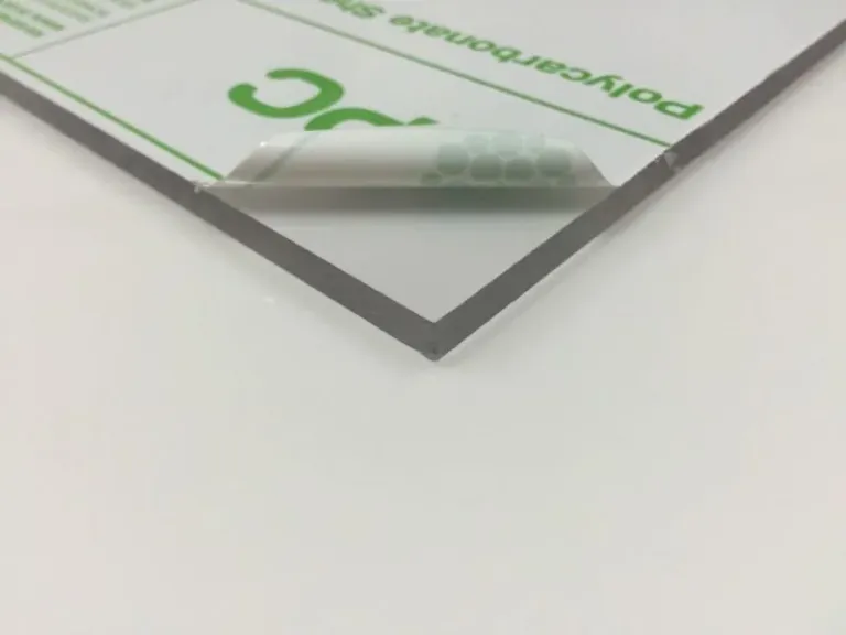
The first decision is the sheet itself: the polymer family and the thickness. We fabricate acrylic, polycarbonate, PETG, HDPE, PVC, and MDF, and projects routinely incorporate metal, wood, and hardware where the design calls for them — but for the rest of this guide, assume acrylic, since that is where the chain’s interactions are sharpest. (If the part exists to absorb impact or live in the cold, read our acrylic vs polycarbonate comparison before going further; material family is the one decision this guide cannot walk back for you.)
Thickness deserves more respect than it usually gets, for two reasons.
First, thickness has tolerance. Per the published table, sheet thickness runs approximately ±10% of nominal. That is a property of how sheet is manufactured, not of how it is fabricated, and no downstream process removes it. The design consequence: never build a critical stack-up on the assumption that nominal thickness is actual thickness. A slot sized to receive a mating panel at exactly nominal will bind on a thick sheet and rattle on a thin one. Slots, dadoes, and captured-panel joints should be designed to accept the thickness range, or flagged so the shop can fit them to the material actually on the saw.
Second, thickness propagates downstream. It sets the part’s stiffness and span behavior, which decides whether a shelf needs a formed return or a support. It sets how a laser edge behaves — more on that at step 2. It sets bend radii at forming, joint proportions at bonding, and the weight the base has to carry. Choosing thickness last, after the geometry is drawn, is designing the chain backwards.
One more note at this step: if your program has a preference about forming stock — some customers do — say so at the quote. Customer material preference on forming is honored where practical, and the time to state it is before the material is ordered, not after.
Step 2: cut method — saw, CNC, or laser
Every flat feature on the part gets cut by one of three processes, and each carries its own published accuracy band:
- Saw cutting: approximately ±1/16″ to ±1/8″. The workhorse for straight blanks, rips, and panels whose edges will be captured, bonded, or finished further.
- CNC routing: approximately ±1/32″. Curves, pockets, holes, interior cutouts, and profiles at consistent accuracy across the whole sheet, in any thickness the machine can hold.
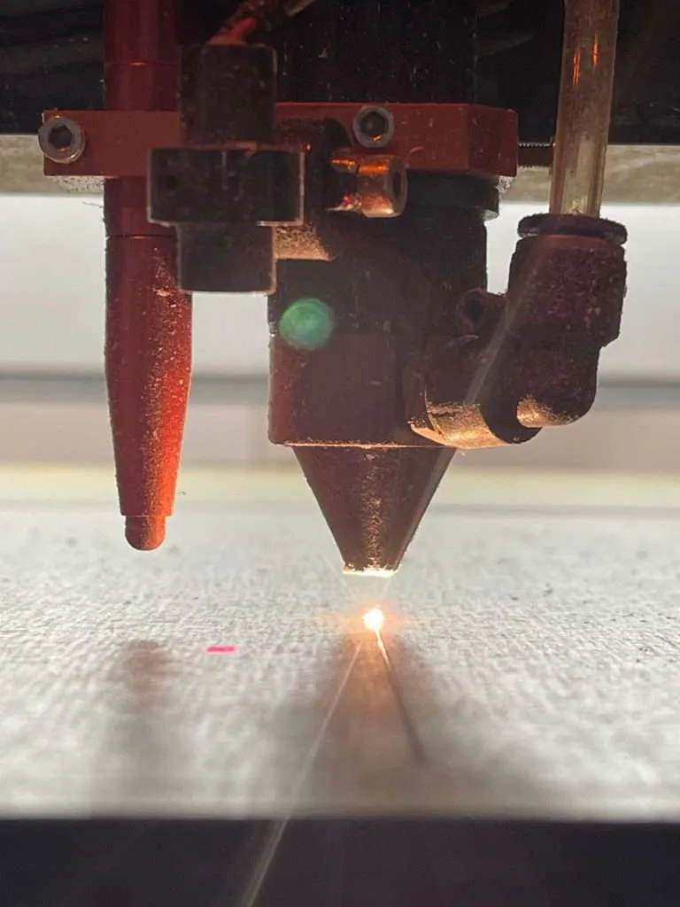
- Laser cutting: approximately ±1/32″ to ±1/64″. The tightest band of the three, plus a finished edge straight off the machine.
The tolerance bands alone would make this an easy ranking, but the chain is not that simple, because each process leaves a different edge — and the edge is an input to steps 4 and 5.
A laser edge comes off the machine glossy, with a slight taper that grows with material thickness; the process is most effective on thinner stock. For a display-facing profile in thin material, that is close to a free polish. But that same glossy edge was made with heat, which means it carries thermal stress — a fact that matters enormously if the edge is later a bonding face. A sawn edge is matte and toolmarked, which sounds worse until you remember that edges inside joints and behind other panels need no cosmetic work at all, and a saw blank is the cheapest square foot of cutting in the shop. A routed edge sits between: accurate, uniform, machined-matte, and an excellent starting point for mechanical polishing.
The design move at this step is to stop specifying one cut method for the whole part. Specify the requirement per feature — this profile is cosmetic and tight, this blank is structural and hidden — and let the tolerance bands map features to processes. Which brings up the single most expensive habit in acrylic drawings.
Tolerance discipline: tight where it functions, default everywhere else
A blanket title-block tolerance of ±1/64″ on an acrylic part is not a conservative drawing. It is an instruction to treat every edge of the part — including the four sides of a rectangular blank that will disappear into a bonded base — as laser work at laser accuracy, or to reject saw and router work that would have served perfectly. It forces the tightest process onto every feature, including the features that would never have noticed the difference.
The discipline that works instead:
- Identify functional features — the ones where accuracy does a job. Mating slots. Hole patterns that must land on hardware. Profiles that register against another part. Sightline edges where a gap would show.
- Tolerance those explicitly, at the band the function actually needs — and check that band against the published table so the callout lands inside a real process capability rather than between them.
- Default everything else. Let the remaining features ride the per-process bands; a general note referencing the Fabrication Tolerances standard covers the rest of the part honestly, and both sides of the purchase order now agree on what “in spec” means.
Two bands from the table deserve special attention because they surprise designers coming from machining. Fabricated assemblies carry approximately ±1/16″ to ±1/8″ — an assembled acrylic case is a stack of parts and joints, and its overall envelope reflects that stack, so critical interfaces should be dimensioned on parts, not on the assembled outside. And thermoformed dimensions run approximately ±3% to ±5% of the formed dimension depending on geometry — a percentage, not a fixed band, which is the subject of the next step.
Step 3: forming
Forming — from a simple heated line bend that turns a flat panel into an L or a J, to full thermoforming over a mold — is where the chain’s stakes rise, because heat changes the material’s dimensional story. Flat features cut before forming were placed at cutting accuracy; the formed dimension itself now carries the approximately ±3% to ±5% band, and that percentage scales with size. On a small formed return the band is small in absolute terms. Across a long formed dimension it is not, and pretending otherwise on the drawing guarantees a rejection dispute.
Three design rules fall straight out of this:
- Feature placement: keep critical features off the bend. A hole pattern or slot near a formed region rides the forming tolerance, not the cutting tolerance it was made at. Put registration features in flat zones, well clear of the heat-affected line, and they keep their cutting-process accuracy.
- Functional datums: decide what the formed part must do — the shelf’s usable depth, the face’s presented height — and dimension those, letting the non-functional legs float within the band.
- Bends over joints: where either would do, prefer the bend. A formed corner is one part with no seam, no solvent, and no joint to inspect. When the geometry allows it, forming removes an entire downstream step — the cheapest kind of DFM there is. The trade is the looser dimensional band; that is a real trade, and which side wins depends on whether the corner’s job is structural continuity or dimensional precision.
Forming also deposits stress in the material near the heated zone. Hold that thought; it is about to matter.
Step 4: joining — solvent bond or mechanical fastening
Where forming cannot make the geometry, parts get joined, and the decision has exactly two honest branches.
Solvent bonding is not glue in the adhesive-layer sense. The solvent temporarily softens both faces and they fuse as it flashes off — a chemical weld that makes the two parts continuous material at the joint. It is permanent, it is the invisible option, and it is the joint by which clear work is judged. Because the joint is optical — you look through acrylic, so you look through its joints — we spec and inspect bonded work against our Acrylic Joint Clarity Standards rather than against adjectives. If a seam sits on a sightline, that standard is what the drawing should reference.
Solvent bonding is also where the chain bites hardest, through a mechanism worth understanding rather than memorizing. Heat leaves internal stress in acrylic — from the laser’s cut, from a flame polisher’s torch, from the forming oven. A stressed surface holds that energy in tension until something releases it, and solvent is exactly that something: it softens the surface, the locked-in stress relieves itself locally, and the face crazes into a web of fine cracks precisely where you needed optical perfection. This is why a bonding face is prepped for its job — stress-free preparation is chosen per joint — and why the sequencing rule is absolute: decide which edges will be bonded before deciding how edges get finished. A drawing that flame-polishes all edges and then bonds four of them has specified a defect.
Mechanical fastening — screws into hardware, standoffs, captured panels — trades appearance for serviceability. The joint is visible and the hardware is part of the design language, but the assembly comes apart: panels swap, graphics update, damaged components replace without scrapping the unit. For a display program with rotating printed inserts, that is not a compromise; it is the point. Two rules make mechanical joints in acrylic survive: give fasteners clearance rather than threading them tight against the material, because acrylic moves with temperature and a rigidly pinned panel will crack at the hole when it tries to; and keep holes away from edges, where the material’s notch sensitivity is least forgiving.
The framework, compressed: permanent and invisible — solvent, judged by Joint Clarity, with stress-managed prep. Serviceable and visible — mechanical, with movement clearance. Mixing the criteria (specifying solvent joints on a unit that needs field service, or hardware on a sightline seam) is a requirements error, not a fabrication one.
Step 5: edge finish
By this point in the chain, most edge-finish decisions have already been made for you — which is exactly why edge finish sits fifth and not first. Bonding faces are constrained by step 4. Hidden and captured edges need nothing beyond their cut. What remains are the visible, non-bonded edges, and those should be specified by named classification — our Edge Finishing standards define six, from Raw/Saw-Cut through Diamond-Polished — against the cosmetic grade the piece must hit.
Grade is the other half of that sentence. Our Quality Standards grade finished work by Inspection Distance — the distance at which the piece must show no visible cosmetic defects: approximately 4 feet for Production Finish, approximately 2 feet for Display Finish, approximately 1 foot for Museum Archival Finish. The published guidance maps them to typical edge treatments: Production Finish commonly carries flame-polished or sanded edges, Display Finish commonly buff-polished, Museum Archival often diamond-polished. The design move is to set the grade from the part’s real viewing distance — a countertop unit is a 2-foot object; a floor display reads from 4 — and let the grade pull the edge spec, rather than specifying the highest-sounding finish on every edge of a part nobody approaches.
Step 6: print
Graphics come last in the chain because they inherit every tolerance above them. Ink placed on a panel registers to the panel’s edges, which carry the cutting tolerance; a printed panel that then gets formed puts fixed graphics on a dimension that moves. Where the sequence allows, cut-then-print keeps registration honest, and graphics that bleed past a cut line or hold a deliberate margin from it survive edge variance gracefully — graphics that are supposed to end exactly at the edge do not.
Second-surface printing — ink on the back face of clear material, read through the sheet — is the move that makes acrylic graphics look like they are inside the part, and it protects the ink behind the full thickness of the material for the life of the display. It costs you mirrored artwork and demands that the first surface stay flawless, which quietly raises the effective grade of that face. On color: we run color-managed CMYK printing matched to the customer’s brand references, proof-approved — so the brand reference belongs in the quote package, and the proof is the gate before a program run, not a formality after it.
Sheet yield: the cost driver hiding in your dimensions
Acrylic is bought and cut as standard sheet sizes, and that single fact makes part dimensions a cost factor in a way that surprises designers pricing by area. What the program pays for is sheets consumed, not square inches used — so the question that matters is how many parts nest into a sheet, and that number moves in steps, not smoothly.
A deliberately invented example, because the mechanism matters more than any particular figure. Suppose a display’s back panel nests six-up on the standard sheet your fabricator stocks, with a modest offcut. Now the panel grows one inch in width — a change nobody would flag in a design review. If that inch pushes the layout past what the sheet width can hold, the nest drops from six parts per sheet to four. Material consumption per part just rose fifty percent, the offcut got bigger and less usable, and nothing about the design got better — the dimension simply stopped cooperating with the sheet. The same inch removed can run the trade in reverse and buy a program a meaningful material saving at zero cost to the design intent.
The practical discipline: on recurring work, treat major part dimensions as soft until yield has been checked. Ask the fabricator where the yield steps fall for your parts at quote time — it is a five-minute nesting question with the drawing in hand — and find out whether an invisible dimension change moves the program a step in either direction. This is also, incidentally, why two nearly identical designs can carry meaningfully different material intensity: one of them was drawn with the sheet in mind.
Worked example: a countertop display through the chain
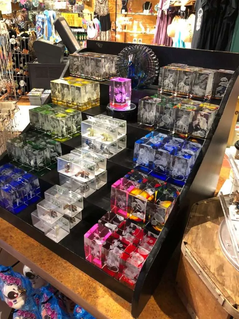
Take a hypothetical program — the numbers are illustrative, invented for the walk-through: a retail countertop display, roughly 16″ wide and 14″ tall, with a printed back panel, an angled product shelf, and a small base, at a few hundred units per run.
Material and thickness. Clear acrylic; the display is a cosmetic object at conversational distance and impact is not a requirement. The shelf span at 16″ is the stiffness question — thin material would sag under product across that width, so the shelf drives the sheet up a thickness step even though the back panel alone would not. One thickness for all parts keeps the program on one sheet stock, which matters at step seven of this example. The shelf’s support slot is designed to accept the approximately ±10% thickness band rather than nominal.
Cut method. The back panel and base are rectangles: saw blanks at approximately ±1/16″ to ±1/8″, perfectly adequate because every one of those edges is either bonded, captured, or bottom-facing. The shelf’s front profile is curved and customer-facing: that edge is laser-cut, buying the approximately ±1/32″ to ±1/64″ band and a glossy edge in the same operation — and this thickness is still comfortably in the range where the laser’s slight taper stays unobtrusive.
Forming. The shelf’s angle could be a bonded joint or a line bend. The bend wins: one part instead of two, no seam on the surface product sits on, no solvent operation per unit across a few-hundred-unit run. The formed return rides the approximately ±3% to ±5% band — acceptable, because the shelf’s functional dimension is its presented depth, which is dimensioned as the datum, while the return leg floats. The shelf’s locating tabs sit in the flat zone, clear of the bend, keeping their laser accuracy.
Joining. Back panel to base is permanent and on a sightline: solvent-bonded, specced against Joint Clarity, which means those mating edges are prepped stress-free for bonding — and it means we did not flame-polish them, and the laser-cut shelf profile is nowhere near a bonding face. The shelf itself locks in with tabs into slots: the one serviceable interface, because shelves are what break in the field.
Edge finish. A countertop unit is a Display Finish object — approximately 2-foot inspection distance. The laser-cut shelf profile is already there. The back panel’s exposed top edge gets buff-polished per the Display guidance. Bonded and bottom edges stay as cut, because paying to polish an invisible edge is how budgets leak.
Print. The back panel graphic prints second-surface, mirrored, after cutting and before assembly: registration to laser-accurate edges, ink protected behind the material, brand color run color-managed CMYK against the customer’s references and proof-approved before the program run.
Yield check. The nesting pass at quote time finds the back panel sits one inch away from a yield step on the stocked sheet. The graphic holds a margin, the design intent survives at 15″, and the program’s material consumption drops a step. That conversation took minutes because it happened before the drawing froze — which is the entire argument of the next section.
Files that quote cleanly
The fastest path from drawing to accurate quote is a file the estimator can read without interpretation. For geometry, PDF is preferred — a dimensioned PDF communicates intent, tolerance callouts, and finish notes in one artifact — and DXF/DWG are accepted where the cutting geometry itself should transfer directly. For print artwork, send AI, EPS, or SVG for vector art, PNG or JPG for raster, along with the brand references the color match will be managed against.
Whatever the format, the drawing should carry the chain’s outputs explicitly: material and thickness; per-feature tolerance callouts on functional features with the standards reference covering the rest; which edges bond and which show; edge classifications by name; grade by Inspection Distance; and print surface (first or second) with bleed or margin intent. A drawing that answers those questions gets a quote instead of a question list.
Involve the fabricator before the drawing freezes
Every decision in this guide is cheap at the drawing stage and expensive after it. The yield step, the bend-versus-bond call, the tolerance that lands between process bands, the flame-polish specified on a bonding face — each is a five-minute conversation before the design is frozen and a re-quote, a re-draw, or a rejected first article after it. The pattern across all of them is the same: the shop can only optimize the decisions that are still open when it first sees the part.
One scheduling note belongs in the same conversation, because capacity is a chain constraint too: of our production tiers, only Reserved Production allocates dedicated capacity to guarantee a specific ship date, so a program with a hard in-store date should say so at the quote, not at the purchase order.
So the close is simple: send the drawing before it’s frozen. A PDF with open questions marked beats a finished drawing with the wrong ones already answered — and it is the single highest-leverage step in this entire chain.