Here is the fact that sinks more formed-part drawings than any other: thermoforming does not add material, it redistributes it. A sheet of acrylic enters the oven with a fixed volume, gets stretched over or into a mold, and whatever depth the part gains, the walls pay for. Finished wall thickness on a formed part is a distribution — thickest where the sheet barely moved, thinnest where it traveled farthest — and no process note on a drawing changes the arithmetic.
Where the material goes
Picture the sheet as a fixed budget being spent across the part’s surface area. A shallow tray spends it almost evenly. A deep draw — a tall cover, a deep bin, a dome — spends heavily on the way down: the sidewalls stretch, and the corners, where material is being pulled in two directions at once, stretch most of all. The result is systematic, not random. The flange and the regions near the clamp stay close to the starting thickness; the deepest sections and the corners land thinnest. Every former knows this curve; the drawing just has to acknowledge it.
This is why the classic failing callout — one uniform finished wall dimension applied everywhere on a deep part — specifies a part that thermoforming does not produce. A buildable drawing controls the starting thickness and the geometry, and the distribution follows; asking a stretching process to behave like a molding process is the only thing that drawing gets wrong.
What to specify instead
The controllable inputs are the starting sheet thickness and the mold geometry. Those two, plus the forming method, determine the thickness distribution — so those are what a buildable drawing controls:
- Starting thickness: call it out, chosen so that the thinnest resulting region still does its structural job.
- Minimums where load-bearing. If one region genuinely needs a floor — a mounting boss, a stressed corner — call a minimum there, not a uniform wall everywhere. A minimum at the critical point is checkable; a uniform wall on a deep part is fiction.
- Formable geometry. Generous radii where the design allows them let material flow instead of starving the corner; sharp internal corners are where deep parts get thin first.
- State the duty — the load, the span, the handling — and let the forming plan be engineered to it. Depth relative to footprint drives how much thinning the geometry will see, and when the geometry looks like a problem, the process planning every quote gets will flag it; a drawing that states the duty gives that flag something real to check against.
When the deep thin section is the problem
Sometimes the honest flag is that the draw is deep enough the thin regions look like a problem for the duty at any sensible starting thickness. The alternatives are standard moves, and good ones:
Split and bond. Build the deep form as two shallower formed sections — or a formed section on a flat body — joined with a bonded seam placed where the design can carry it. Each piece draws less, so each keeps more of its thickness. Joint placement and appearance follow the usual bonding logic.
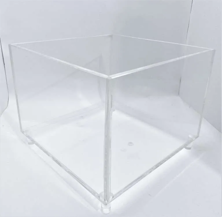
Fabricated construction. Some “formed” parts are better built as cut-and-bonded assemblies — flat panels, machined edges, bonded corners. A fabricated box keeps full sheet thickness everywhere, at the cost of visible construction; a formed cover gets seamless flow, at the cost of thinning. Which wins is a design decision, and it’s cheaper to make at the drawing stage than after a first article. Simple single-axis curves often want line bending instead of a full draw — a bend barely thins at all compared to a deep form.
Form for stiffness. If the thin wall’s job was rigidity rather than strength, geometry can do the work material was being asked to do: formed ribs, returns, and profile changes stiffen a part without thickening it.
The tolerance side of formed parts
Formed parts also carry their own dimensional logic. Our published Fabrication Tolerances standard lists thermoformed components at approximately ±3% to ±5% depending on geometry — deliberately wider than the machined ranges, because a stretched and cooled part moves in ways a routed edge does not. The practical consequences: dimension the formed part from its tooling-controlled features, expect the formed ranges on the formed dimensions, and put machined tolerances only on features that get machined after forming — trimmed edges, drilled holes, routed openings, which is how formed parts get their precision interfaces. Once the tooling is locked, the distribution is repeatable across the run: part forty thins where part one thinned, which is what makes a formed production run consistent. The fuller process-by-process picture is in fabrication tolerances by process.
The short version for the next drawing: spec the starting thickness and the duty, put minimums only where they earn their place, give corners radii, and let the forming review tell you if the geometry wants to be two pieces. Formed acrylic rewards designers who work with the stretch instead of legislating against it — the rest of that mindset is in the engineer’s guide to designing for acrylic fabrication.