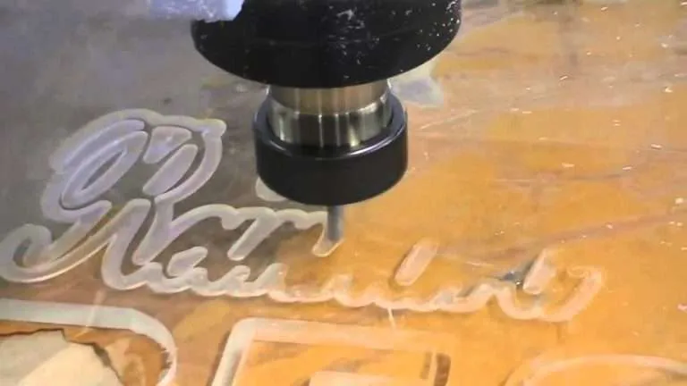
Here is the mental model that explains most of what a custom acrylic quote does: machine time is cheap, and hand labor is not. A CNC or laser pass costs minutes and produces the same result every time. A polished edge, a bonded joint held to the unit’s finish grade, a hand-finished detail — those cost a person’s attention, piece after piece. Every one of them is a decision the designer makes at the CAD stage, usually without knowing a decision was being made. This post makes the decisions visible.
The effort drivers, ranked
Polished-edge inches. The single biggest lever on most display-class parts. Each edge that gets polished is handled, finished and inspected edge by edge, so the question is never “polished or not” for the part — it’s which edges genuinely face the viewer. A countertop unit seen from the front has front and side edges in the sightline; the back edge and every concealed edge can stay at the raw or saw-cut finish the standard defines for exactly that case, with no shopper ever knowing. The Edge Finishing Standards give you six named methods to assign per edge, which is precisely what makes per-edge specification possible.
Bonded-joint count and clarity expectations. Every joint is assembly labor, and the standard it’s held to multiplies it: a joint built to Museum Archival expectations takes more preparation, more care in cementing and more inspection than one built for a Production Finish unit, which is exactly what the Joint Clarity Standards exist to make specifiable. Fewer joints, and a stated inspection condition per joint, both show up directly in effort.
Thickness jumps mid-assembly. Each thickness in an assembly is its own material pull, its own machine setup and its own edge-finishing behavior. Two thicknesses are often justified; four thicknesses in one unit should prompt the question of whether the design earned them.
Tight inside radii. Small inside corners force tool changes and slower feeds on the CNC. If the corner radius isn’t functional — if nothing nests into it — letting it grow to the cutter’s natural radius removes machining time with zero visual consequence.
Tolerances tighter than the function. A blanket tight tolerance copied from a machined-parts template routes features to slower processes for nothing. The published fabrication tolerances are stated per process — laser-cut components run approximately ±1/32″ to ±1/64″, CNC-routed approximately ±1/32″, saw-cut approximately ±1/16″ to ±1/8″ — so a callout tighter than the process range is a process decision, whether or not it was meant as one. Which process carries which range is worth five minutes before any callout tighter than the default.
The free choices — spend them
Some of what designers ration costs nothing, because it rides along with a machine pass that was happening anyway:
- Color. Standard catalog colors cut like clear sheet. The design impact of a fluorescent edge or a black base is bought at the material line, not in labor.
- Profile complexity in a single cut pass. A curved, sculptural outline and a rectangle take roughly the same machine attention. Complexity of the cut path is close to free; complexity of the finishing that follows it is not — a sweeping curve on a polished display edge is more polishing, so put the drama on edges that stay machine-finished.
- Engraved detail in the same fixturing. Engraving added while the part is already on the machine is a second operation, not a second setup.
- Hole count, within reason. Drilled patterns are machine work; what deserves the attention is edge distance and hole oversizing, not the count.
One part, specced two ways
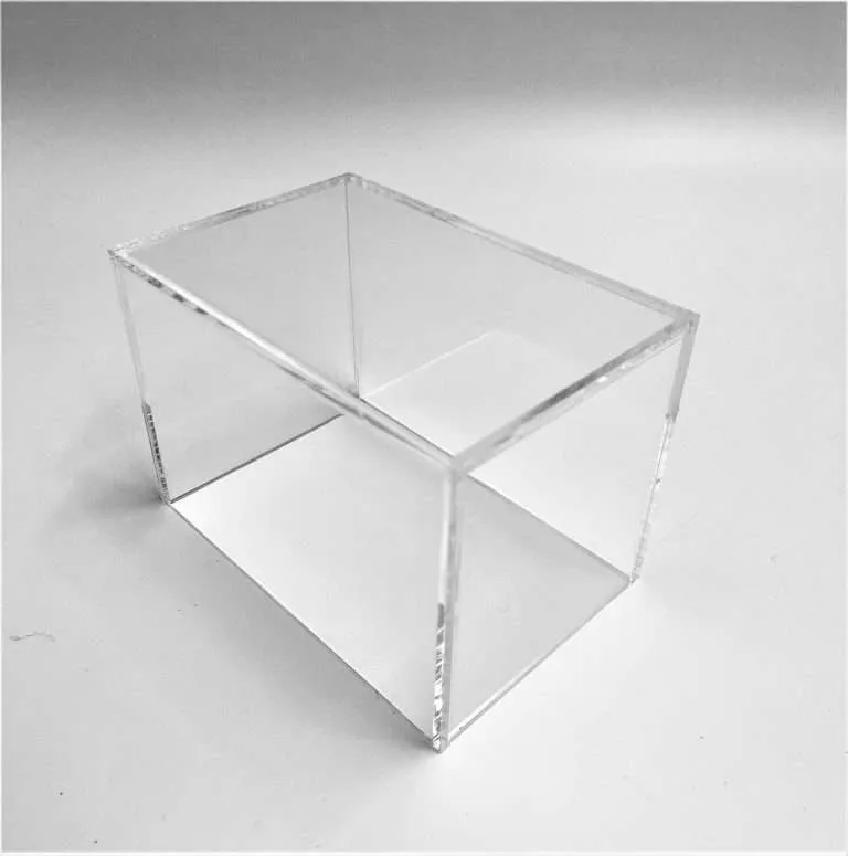
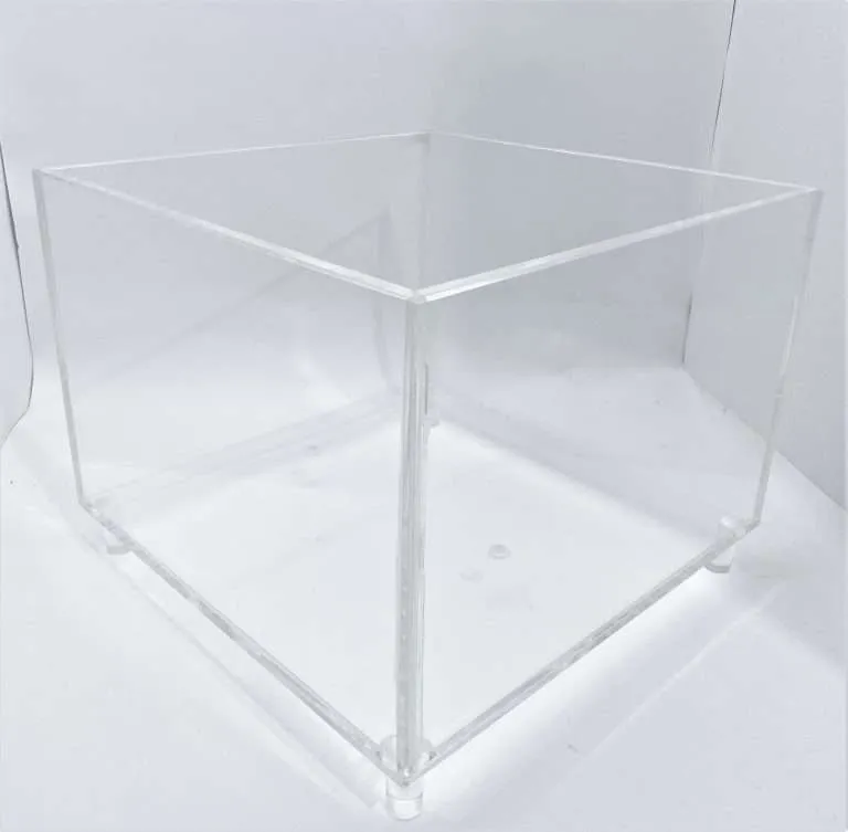
Take a simple bonded countertop riser — a five-sided box, product on top, logo panel on the front. Spec A: all edges polished, every joint held to Museum Archival expectations, overall dimensions toleranced to ±1/64″. Spec B: front and side top edges polished for a Display Finish unit, back and bottom edges left raw or saw-cut, the two front joints called out tight on the drawing and the rest built to the unit’s grade, general tolerances per the published saw/CNC ranges with one tight callout on the product-well dimension.
In the shop, Spec A means every edge handled and polished, every joint prepared and inspected to the top grade, and features pushed to slower processes by the blanket callout. Spec B means the polishing and joint attention land only where a shopper’s eye does, the machine does everything else, and the one dimension that affects product fit is the one dimension held tight. The two parts look identical on the counter. They are not the same amount of work — and only one of them was designed to be the work it needs to be.
Why this pre-qualifies your quote
A drawing that distinguishes cosmetic faces from functional faces, grades edges and joints in the published standards vocabulary, and tolerances only what the function needs is a drawing the quote desk can price without a round of questions — which is most of what makes a quote fast and accurate. It also signals something real about the project: that effort has been pointed where it pays. We’ll flag the same things from our side — telling a customer when a small change cuts cost is part of the job — but the version where the drawing arrives already pointed is faster for everyone. The RFQ drawing checklist covers what else belongs on the sheet, sheet yield covers the other big effort lever (material), and the DFM mistakes post is the list of what not to do. The full engineer’s treatment lives in the design-for-fabrication guide.
If you’re staring at a model deciding which edges to call polished: that conversation is cheap at the drawing stage and expensive after the quote. Have it with us early.